Multilevel Inverter Topologies for High-Power Applications: Analysis, Comparison, and Emerging Trends
Conventional two-level voltage source inverters, while dominant in low and medium-power applications, face significant limitations when power ratings extend into the megawatt range and voltage requirements reach medium voltage levels (2.3kV to 13.8kV). These limitations include high dv/dt stress on motor windings, large filter requirements, electromagnetic interference, and challenges in series connection of switching devices to achieve higher voltage ratings. Multilevel inverters emerged in the 1970s as an elegant solution to these challenges, synthesizing staircase voltage waveforms from multiple DC voltage levels to approximate sinusoidal outputs with superior harmonic performance.
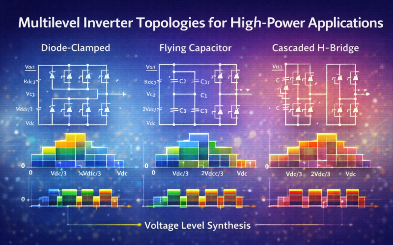
This article provides a comprehensive examination of multilevel inverter topologies, beginning with the fundamental concepts that distinguish multilevel inverters from conventional two-level designs. We explore the three classical topologies—diode-clamped, flying capacitor, and cascaded H-bridge—analyzing their operating principles, advantages, limitations, and typical applications.
The increasing deployment of renewable energy systems, particularly solar photovoltaic and wind power generation, has renewed interest in multilevel inverter technology. Grid-tied inverters for utility-scale solar farms frequently employ multilevel topologies to meet grid code requirements while minimizing filter costs. Similarly, medium-voltage motor drives for industrial applications such as mining, oil and gas, and marine propulsion increasingly utilize multilevel inverters.
Fundamental Principles of Multilevel Inverters
Author: Geetha Editorial Team
Published: Oct 13, 2025
Last Updated: Feb 13, 2026
Basic Concept and Benefits
The fundamental principle of multilevel inverters is the synthesis of a desired AC voltage waveform from multiple discrete DC voltage levels. While a conventional two-level inverter produces output voltage waveforms with only two values (+Vdc and 0, or +Vdc/2 and -Vdc/2 depending on configuration), a multilevel inverter with N levels can generate N distinct voltage levels, creating a staircase waveform that more closely approximates a sinusoidal output.
Consider an m-level inverter phase leg with m voltage levels. As the number of levels increases, the synthesized waveform approaches a pure sinusoid, reducing harmonic content and improving power quality.
The benefits of multilevel operation include:
- Lower harmonic distortion: The staircase waveform contains significantly lower harmonic content than a two-level waveform, reducing or eliminating the need for large, expensive output filters. For an m-level inverter, the dominant harmonics appear at frequencies m times the fundamental.
- Reduced dv/dt stress: The voltage steps in a multilevel inverter are smaller (Vdc/(m-1)) compared to the full DC bus voltage in a two-level inverter. This reduces electromagnetic interference, cable stress, and bearing currents in motor drives.
- Higher voltage capability: Multilevel topologies enable medium voltage operation without series connection of switching devices, avoiding the complex voltage balancing and gate drive synchronization required for series-connected devices.
- Improved efficiency: The combination of lower switching losses and reduced filter losses can yield higher overall efficiency, particularly in high-power applications.
- Fault tolerance: Some multilevel topologies, particularly modular configurations, offer inherent redundancy. A single failed module can be bypassed, allowing continued operation at reduced output voltage.
Voltage and Current Stress Analysis
A critical advantage of multilevel inverters is the distribution of voltage stress across multiple devices. In a two-level inverter operating at DC bus voltage Vdc, each switch must block the full voltage Vdc. In contrast, for an m-level diode-clamped or flying capacitor inverter, each switch blocks only Vdc/(m-1).
For example, in a five-level inverter (m=5) operating at 4.16kV DC bus voltage, each switch blocks only 4.16kV/4 = 1.04kV, allowing use of 1.7kV semiconductor devices with adequate margin. This enables medium voltage operation using conventional IGBT or MOSFET devices without series connection.
Current stress distribution depends on the specific topology and operating conditions. In diode-clamped inverters, clamping diodes carry unequal currents depending on their position in the voltage divider chain. Flying capacitor topologies distribute current more evenly across devices.
Harmonic Analysis
The harmonic content of multilevel inverter output waveforms can be analyzed through Fourier analysis. For a staircase waveform synthesized from m levels, the Fourier series expansion reveals that low-order harmonics are significantly attenuated compared to a two-level waveform.
The total harmonic distortion (THD) of an m-level inverter output voltage decreases approximately as 1/(m-1)². For example:
- 3 levels: THD ≈ 31%
- 5 levels: THD ≈ 12%
- 7 levels: THD ≈ 6.5%
This relationship explains why even modest increases in level count yield significant harmonic performance benefits.
The dominant harmonics in a multilevel waveform appear at frequencies that are multiples of (m-1) times the fundamental frequency. For a 5-level inverter operating at 60Hz fundamental frequency, the dominant harmonics appear near 240Hz (4×60Hz) and its multiples. This high-frequency content is much easier to filter than the low-order harmonics present in two-level waveforms.
Classical Multilevel Topologies
Diode-Clamped (Neutral-Point-Clamped) Inverter
The neutral-point-clamped (NPC) inverter, introduced by Nabae, Takahashi, and Akagi in 1981, represents the first practical multilevel inverter topology and remains widely used in industrial applications. The three-level NPC inverter serves as the archetype for understanding diode-clamped topologies.
Each phase leg of a three-level NPC inverter consists of four switching devices (typically IGBTs) in series with their antiparallel diodes, along with two clamping diodes that connect the middle point of the series switches to the neutral point of a split DC bus. The DC bus consists of two series capacitors with their midpoint serving as the neutral point.
By appropriate control of the four switches in each phase leg, three distinct voltage levels can be generated:
- +Vdc/2 (both upper switches ON)
- 0 (both middle switches ON, with current flowing through clamping diodes)
- -Vdc/2 (both lower switches ON)
Advantages of the NPC topology:
- Well-established and proven technology with decades of industrial deployment
- Efficiency comparable to or better than two-level inverters
- Simplified DC bus structure requiring only two series capacitors
- Commercially available modules integrating all necessary components
Limitations:
- Unequal loss distribution among switching devices, with inner devices experiencing higher losses
- Difficulty in balancing neutral point voltage, particularly at low power factors
- Clamping diode voltage and current ratings increase rapidly with additional levels, limiting practical implementations to three or occasionally five levels
- Large, expensive DC bus capacitors required for neutral point voltage stabilization
The three-level NPC topology has achieved significant commercial success in medium-voltage drives (2.3-7.2kV) and renewable energy applications. Modern variants including the Active NPC (ANPC) and T-Type NPC topologies address some limitations through alternative switching device arrangements.
Flying Capacitor Inverter
The flying capacitor or capacitor-clamped multilevel inverter, introduced by Meynard and Foch in the early 1990s, replaces the clamping diodes of the diode-clamped topology with clamping capacitors. This seemingly simple substitution yields fundamentally different characteristics and capabilities.
A three-level flying capacitor phase leg consists of four series switches with a floating capacitor connected between the midpoints of the upper and lower switch pairs. This floating capacitor charges to Vdc/2, providing the voltage level required to generate the intermediate output voltage.
The key insight of flying capacitor topologies is that multiple redundant switching states can generate the same output voltage while differently affecting capacitor voltages. This redundancy enables control algorithms to actively balance capacitor voltages while synthesizing the desired output voltage.
For an m-level flying capacitor inverter, the number of independent capacitor voltages that must be regulated grows as (m-1)(m-2)/2, requiring (m-1) capacitors per phase leg.
Advantages:
- Natural voltage balancing through redundant switching states, reducing control complexity
- More uniform loss distribution compared to diode-clamped topologies
- Scalability to higher levels (5, 7, or more) limited primarily by cost rather than fundamental constraints
- Excellent ride-through capability during supply disturbances due to energy stored in flying capacitors
Limitations:
- Large number of expensive capacitors, particularly for levels beyond three
- Complex switching pattern generation to ensure capacitor voltage balance
- Pre-charging requirements for capacitors before operation
- Limited commercial availability of integrated modules compared to NPC topology
Flying capacitor inverters find application primarily in specialized high-performance applications where their unique capabilities justify the additional cost and complexity.
Cascaded H-Bridge Inverter
The cascaded H-bridge (CHB) multilevel inverter employs a fundamentally different approach: synthesizing multilevel waveforms by series-connecting the outputs of multiple single-phase H-bridge cells. Each H-bridge can independently generate three voltage levels: +Vdc, 0, and -Vdc. Series connection of n H-bridges per phase yields 2n+1 possible output voltage levels.
For example, a three-cell CHB inverter (n=3) can generate seven distinct voltage levels: ±3Vdc, ±2Vdc, ±Vdc, and 0. The modular structure simplifies manufacturing, reduces spare parts inventory, and enables graceful degradation through bypass of failed modules.
Each H-bridge requires an independent, isolated DC power supply. In photovoltaic applications, individual solar panel strings naturally provide these isolated supplies. In motor drive applications, multi-pulse diode rectifiers or isolated DC-DC converters feed the H-bridges.
Advantages:
- Modular structure enabling flexible voltage scaling and redundancy
- Ease of manufacturing and maintenance due to identical modules
- Excellent harmonic performance with relatively few components
- No complex capacitor voltage balancing requirements
- Straightforward extension to any desired number of levels
Limitations:
- Requirement for isolated DC supplies for each cell
- Higher component count (switches, gate drivers) compared to other topologies
- More complex mechanical and electrical packaging due to separate isolated modules
- Difficult implementation of regenerative (motor braking) operation without active front-end converters
The CHB topology dominates utility-scale photovoltaic applications where series-connected solar strings naturally provide isolated DC sources. Medium-voltage motor drives also employ CHB inverters, particularly in applications requiring very high voltage levels or where redundancy is critical.
Modulation Strategies for Multilevel Inverters
Sinusoidal PWM and Level-Shifted Carrier Methods
Carrier-based PWM represents the most straightforward extension of conventional PWM to multilevel inverters. For an m-level inverter, (m-1) triangular carrier waveforms are compared against the sinusoidal reference signal. The carriers may be arranged with various phase relationships:
Level-shifted PWM uses (m-1) carriers at the same frequency but vertically shifted to occupy different voltage bands. Three main variants exist:
- Phase disposition (PD): all carriers in phase
- Phase opposition disposition (POD): carriers above zero are in phase, those below zero are 180° out of phase
- Alternative phase opposition disposition (APOD): adjacent carriers are 180° out of phase
These different arrangements yield identical fundamental output but different harmonic characteristics. PD arrangement typically provides best harmonic performance for three-phase applications.
Phase-shifted carrier PWM, primarily used with cascaded H-bridge topologies, employs (m-1)/2 carriers at equal frequency but with phase shifts of 360°/(m-1) between adjacent carriers. This spreading of switching events across time reduces current ripple and improves harmonic performance.
Space Vector PWM for Multilevel Inverters
Extension of space vector PWM to multilevel inverters provides superior DC bus utilization and harmonic performance but at substantially increased computational complexity. The space vector diagram for an m-level three-phase inverter contains m³ voltage vectors (compared to 8 for a two-level inverter).
For a three-level inverter, 27 voltage vectors populate the space vector diagram:
- 6 large vectors at the hexagon vertices
- 6 medium vectors at the midpoints of hexagon edges
- 12 small vectors forming an inner hexagon
- 3 redundant zero vectors at the origin
The control algorithm identifies which region contains the reference voltage vector and synthesizes it using the three nearest vectors.
Higher-level inverters yield even more complex space vector diagrams. A five-level inverter produces 125 voltage vectors, making real-time calculation challenging even on modern digital signal processors. Simplified algorithms and lookup table approaches reduce computational burden while maintaining most benefits of space vector control.
Selective Harmonic Elimination
Selective harmonic elimination (SHE) modulation offers an alternative approach particularly suitable for low-switching-frequency applications where minimizing switching losses is paramount. Rather than using high-frequency PWM, SHE generates a staircase waveform with specifically calculated switching angles to eliminate selected low-order harmonics.
For an m-level inverter, there are (m-1)/2 switching angles per quarter period that can be optimized. These angles can be calculated to eliminate (m-3)/2 specific harmonics while controlling the fundamental magnitude. For a seven-level inverter, three angles can eliminate the 5th, 7th, and 11th harmonics while achieving desired fundamental voltage.
The switching angles are typically pre-calculated offline by solving a system of nonlinear equations, then stored in lookup tables for real-time implementation. While SHE produces excellent low-order harmonic performance, it offers no control over high-order harmonics, requiring output filters for complete harmonic mitigation.
SHE finds primary application in high-power medium-voltage drives where minimizing switching frequency and associated losses is critical.
Emerging Topologies and Hybrid Configurations
Modular Multilevel Converter (MMC)
The modular multilevel converter, developed in the early 2000s, represents a significant architectural innovation particularly suited to very high power applications such as HVDC transmission and STATCOM applications. Unlike classical multilevel topologies where all switches connect directly between DC bus and output, the MMC employs chains of series-connected half-bridge or full-bridge submodules with distributed energy storage.
Each phase leg consists of two arms (upper and lower), with each arm containing a series connection of n identical submodules plus a small inductor. Each submodule comprises a half-bridge circuit (two switches and one capacitor) capable of generating either Vdc (capacitor inserted) or 0 (capacitor bypassed). The output voltage is synthesized by appropriate selection of how many upper and lower arm submodules are inserted at any time.
The distributed energy storage in submodule capacitors eliminates the need for a large central DC bus capacitor, a major advantage in high-power applications. Additionally, the modular structure enables very high voltage levels (hundreds of kilovolts in HVDC applications) with excellent scalability.
Key challenges include:
- Complex control requirements to balance all submodule capacitor voltages
- Circulating currents between upper and lower arms that must be controlled
- Large number of sensors and gate driver circuits
- Energy management during transients and faults
Despite these challenges, MMC technology has become the dominant topology for new HVDC installations and is finding increasing application in large STATCOM and motor drive applications.
Hybrid Multilevel Topologies
Recognition that no single multilevel topology optimally addresses all requirements has motivated development of hybrid configurations combining features of multiple classical topologies. Common hybrid approaches include:
Asymmetric cascaded H-bridge inverters employ H-bridge cells with different DC voltages, typically in ratios of 1:3 or 1:4. This enables generation of many voltage levels using fewer cells than symmetric configurations. A two-cell asymmetric CHB with DC voltages of Vdc and 3Vdc can generate 9 levels (±4Vdc, ±3Vdc, ±2Vdc, ±Vdc, 0), equal to a four-cell symmetric configuration.
Hybrid CHB/NPC configurations use three-level NPC cells as building blocks for cascaded architectures, combining the proven reliability of NPC cells with the modular scalability of cascaded topologies. This approach is particularly common in high-power solar applications.
Practical Implementation Considerations
Device Selection and Thermal Management
Component selection for multilevel inverters requires careful consideration of voltage, current, and thermal constraints. While multilevel operation reduces per-device voltage stress, device utilization and loss distribution vary significantly between topologies.
In NPC inverters, the inner switches and clamping diodes experience higher losses than outer devices, creating thermal management challenges. Either all devices must be rated for the worst-case dissipation or custom thermal designs must accommodate non-uniform heat generation.
Silicon carbide (SiC) devices offer particular advantages in multilevel inverters due to their lower switching losses and higher temperature capability. The reduced voltage stress per device in multilevel topologies aligns well with SiC device ratings (typically 1.2-1.7kV), enabling all-SiC multilevel inverters that further improve efficiency and power density.
Capacitor sizing and selection critically impacts reliability and cost. Flying capacitor inverters require large, expensive film capacitors. DC bus capacitors in all topologies must handle ripple currents while maintaining voltage regulation.
Control Platform Requirements
Modern multilevel inverter control requires substantial computational capability. Tasks include:
- Real-time PWM generation (carrier comparison or space vector calculations)
- Current and voltage feedback processing
- Voltage balancing algorithms
- Protection monitoring and fault response
- Communications with supervisory systems
Digital signal processors (DSPs) and field-programmable gate arrays (FPGAs) represent the dominant control platforms. DSPs excel at control algorithm execution, while FPGAs provide parallel processing and deterministic timing for PWM generation. Hybrid platforms combining both technologies optimize the strengths of each approach.
Control loop update rates typically range from 10-20kHz for large multilevel inverters to 50-100kHz for smaller systems.
Protection and Fault Management
Multilevel inverters require comprehensive protection against faults including:
- Switch failures (short-circuit and open-circuit)
- DC bus overvoltage and undervoltage
- Capacitor voltage imbalance
- Output overcurrent and short-circuit
- Thermal overload
Modular topologies like CHB offer graceful degradation capabilities. Upon detection of a cell fault, the control system can bypass the failed cell and continue operation at reduced output voltage. This requires (n+1) cells to guarantee full rated voltage with one cell failed.
Fast fault detection and protection remain challenging. Short-circuit faults must be cleared within microseconds to prevent device destruction, requiring fast current sensors and protection logic implemented in hardware (FPGA or dedicated protection ICs) rather than software.
Applications and Future Trends
Current Applications
Multilevel inverters have achieved commercial success in several key applications:
Medium-voltage motor drives (200kW to 40MW) employ primarily three-level NPC or cascaded H-bridge topologies for applications including:
- Mining equipment
- Oil and gas processing
- Marine propulsion
- HVAC systems
Grid-tied solar inverters, particularly for utility-scale installations (1-10MW per inverter), increasingly employ multilevel topologies. String inverters with cascaded H-bridge configurations directly interface series-connected solar panels.
HVDC transmission systems use modular multilevel converters for both line-commutated and voltage-source converter configurations. The scalability to very high voltages (±400kV or higher) and excellent harmonic performance make MMC the technology of choice for new installations.
STATCOM and other power quality devices leverage multilevel technology to achieve fast dynamic response with low harmonic injection.
Emerging Trends and Research Directions
Several trends will shape future multilevel inverter development:
- Increased SiC device adoption will enable higher efficiency and power density. As SiC costs decrease, even cost-sensitive applications will transition to all-SiC designs.
- Artificial intelligence and machine learning techniques are being applied to multilevel inverter control, particularly for predictive maintenance, adaptive modulation optimization, and autonomous voltage balancing.
- Integration with energy storage systems will expand as battery costs decline. Multilevel inverters offer natural interfaces to series-connected battery packs.
- Higher levels and new topologies continue to be explored in research, including 9-level, 11-level, and higher configurations for specific applications.
Conclusion
Multilevel inverter technology has evolved from academic curiosity to commercial reality over the past four decades, driven by compelling advantages in medium and high-power applications. The fundamental principle—synthesizing improved waveforms from multiple voltage levels—yields practical benefits including reduced harmonic distortion, lower voltage stress, higher efficiency, and improved reliability.
Multiple competing topologies each offer distinct advantages and limitations. The choice among diode-clamped, flying capacitor, cascaded H-bridge, modular multilevel, and hybrid configurations depends on specific application requirements including power rating, voltage level, harmonic performance, efficiency, cost, and reliability objectives.
Continued advances in power semiconductors, particularly silicon carbide technology, along with improved control platforms and sophisticated modulation algorithms, will further enhance multilevel inverter capabilities. For power electronics engineers working in renewable energy, motor drives, power quality, or HVDC applications, multilevel inverter technology represents an essential tool for addressing challenging high-power, high-voltage applications where conventional two-level inverters prove inadequate.
The maturation of multilevel inverter technology and its increasing commercial deployment across diverse applications confirms its role as one of the most significant power electronics innovations of the past half-century. As power ratings continue to increase and performance requirements become more stringent, multilevel topologies will play an ever-more critical role in the power electronics landscape.
Multilevel Inverter Topologies Comparison
| Topology | Diode-Clamped | Flying Capacitor | Cascaded H-Bridge |
|---|---|---|---|
| Device Voltage Rating | Vdc/(m-1) each | Vdc/(m-1) each | Vdc – lower per module |
| Capacitor Balancing | Inherent | Requires active control | Inherent (isolated supplies) |
| Max Practical Levels | 5-7 | 7-9 | Highly scalable |
| Efficiency | 94-96% | 94-97% | 95-97% |
| THD (Harmonic) | 5-8% | 4-6% | 3-5% |
| Control Complexity | Moderate | High (balancing) | Low-moderate |
| Best Applications | HVDC, power supplies | Industrial drives | Renewable integration |
Key Takeaways
- Multilevel inverters enable high-voltage operation—using multiple lower-voltage components to synthesize high-quality output waveforms.
- Three primary topologies serve different purposes—diode-clamped, flying capacitor, and cascaded H-bridge, each with trade-offs.
- Modulation strategies determine performance—from simple PWM to sophisticated space-vector modulation and nearest-level modulation.
- Harmonic distortion decreases as level count increases—following relationship 1/(m-1)² where m is voltage level count.
- Device stress distribution improves with multilevel topology—enabling higher power handling and better reliability.
- Emerging topologies like modular multilevel converters offer advantages in scalability and fault tolerance.
- Real-world applications span HVDC, renewable integration, and industrial drives—multilevel topology enables future power systems.