AC and DC Circuits: Analyzing Current and Voltage in Electrical Systems
Understanding AC and DC Circuit Analysis
Author: Geetha Editorial Team
Published: Nov 11, 2025
Last Updated: Feb 13, 2026
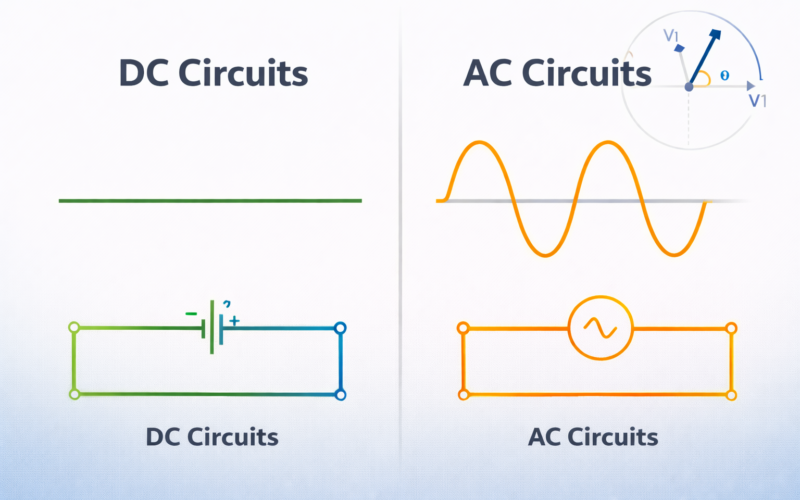
Electrical systems use two types of current: alternating current (AC) and direct current (DC). Understanding the differences between these systems and how to analyze circuits containing each is essential for electrical engineering. While the fundamental principles of Ohm’s Law and Kirchhoff’s laws apply to both, AC analysis introduces additional complexity due to the time-varying nature of AC signals. Modern electrical systems typically use both: AC for power generation, transmission, and distribution; DC for electronics and increasingly for local distribution.
Direct Current (DC) Basics
DC voltage is constant over time. Batteries, solar cells, and electronic power supplies produce DC. DC flows from positive to negative terminals through external circuits (following the conventional current direction).
Analyzing DC circuits is relatively straightforward:
Resistive Elements: Resistors follow Ohm’s Law: V = IR. Resistance is independent of frequency or voltage magnitude.
Capacitors: In steady-state DC, capacitors act as open circuits—no current flows through them. Capacitors block DC but pass AC.
Inductors: In steady-state DC, inductors act as short circuits—they have no resistance to DC current. Inductors block AC but pass DC.
Circuit Analysis Methods: Nodal analysis (applying Kirchhoff’s current law at nodes) and loop analysis (applying Kirchhoff’s voltage law around loops) systematically solve complex circuits. Thévenin’s theorem simplifies circuits by replacing complex networks with equivalent voltage sources and series resistances.
Alternating Current (AC) Basics
AC voltage varies sinusoidally: v(t) = V_m sin(ωt + φ), where V_m is peak voltage, ω is angular frequency (2πf, where f is frequency in Hz), and φ is phase angle.
AC is produced by generators whose coils rotate in magnetic fields. Household AC has frequencies of 50 Hz (most countries) or 60 Hz (North America, some others).
AC enables efficient transmission because voltage can be easily transformed using inductors, reducing transmission losses. This is why AC dominates power systems, despite DC advantages for electronics.
Phasors and Complex Impedance
AC circuit analysis becomes manageable using phasor notation. A sinusoidal signal is represented as a complex number:
v(t) = V_m sin(ωt) ↔ V = V_m/√2 ∠ 0° (in phasor form)
The magnitude V_m/√2 is the RMS (root mean square) value—the effective value of the AC signal. Household AC voltages are specified as RMS values (120V or 240V RMS).
Complex impedance extends Ohm’s Law to AC circuits. Impedance Z = R + jX, where R is resistance, X is reactance, and j = √-1 (imaginary unit).
Resistance: R (independent of frequency)
Inductive Reactance: XL = ωL = 2πfL (increases with frequency)
Capacitive Reactance: XC = 1/(ωC) = 1/(2πfC) (decreases with frequency)
With impedance, Ohm’s Law extends to AC: V = IZ (in phasor form).
AC Circuit Analysis
All circuit analysis techniques used for DC apply to AC using phasors and impedance:
Kirchhoff’s laws apply to phasors just as to DC. Nodal and loop analysis work identically. Thévenin’s theorem applies with impedance replacing resistance.
Resonance: In RLC circuits, resonance occurs at frequency f_0 = 1/(2π√LC), where inductive and capacitive reactances cancel. At resonance, impedance is purely resistive and minimum, and current is maximum. Resonance is fundamental in filters, tuned circuits, and many applications.
Power in AC Circuits: AC power has three components:
Real Power (P) = VI cos(φ) measured in watts—actual power transferred to loads
Reactive Power (Q) = VI sin(φ) measured in VAR—power oscillating between source and reactive elements
Apparent Power (S) = VI measured in VA—combination of real and reactive power
The power factor (cos φ) indicates what fraction of apparent power is real power. Industrial applications strive for near-unity power factor to minimize losses.
AC vs. DC Characteristics Comparison
| Parameter | Direct Current (DC) | Alternating Current (AC) |
|---|---|---|
| Voltage Profile | Constant, unidirectional | Sinusoidal, bidirectional (50-60 Hz) |
| Common Sources | Batteries, solar cells, fuel cells | Power generators, utility grid, outlets |
| Transmission Distance | Short to medium (high losses) | Long distance (efficient with transformers) |
| Voltage Transformation | Requires power electronics (DC-DC) | Simple transformer (no moving parts) |
| Power Loss (I²R) | Higher for same power transfer distance | Lower with step-up transformers |
| Typical Applications | Electronics, vehicles, renewable DC systems | Household power, industrial, utility grid |
| RMS Voltage (120V/240V systems) | Constant 120V or 240V | 120V or 240V RMS = 170V or 340V peak |
| Power Delivery | P = VI (straightforward) | P = VI cos(φ) (includes power factor) |
| Efficiency | Good for short distance, local applications | Excellent for long-distance distribution |
| Equipment Safety | Lower voltage often safer for users | Higher voltage requires careful handling |
Three-Phase AC Systems
Most power generation and transmission uses three-phase AC, where three sinusoidal voltages are 120° apart in phase. Three-phase systems are more efficient than single-phase, providing relatively constant power delivery and requiring less copper for transmission.
Three-phase motors are simple, robust, and efficient—far superior to single-phase motors. Industrial systems worldwide use three-phase AC.
AC-to-DC Conversion
Electronic devices require DC power, necessitating conversion from AC. Rectifiers convert AC to pulsating DC (using diodes), while filters smooth this to nearly constant DC. Voltage regulators maintain constant output voltage despite variations in input voltage or load current.
Modern power supplies use switched-mode designs, where input AC (or DC) is rapidly switched on and off at high frequency. This enables efficient voltage conversion and step-down or step-up as needed.
AC vs. DC Transmission
AC Advantages: Easy voltage transformation (enabling efficient transmission), inductive coupling for isolation, compatible with three-phase systems, established infrastructure worldwide.
DC Advantages: No reactive power, better stability for interconnected systems, lower electromagnetic emissions, increasingly used for long-distance transmission (HVDC—high voltage DC) and renewable energy systems.
Modern Electrical Systems
Future systems will increasingly blend AC and DC. Renewable energy sources (solar, wind) naturally generate variable frequency power, best managed with DC. Microgrids with local generation and storage benefit from DC distribution. However, AC remains fundamental to the bulk power system.
Smart Grids: Modern electrical grids use real-time monitoring and control. Understanding AC and DC circuits remains essential for engineers managing these complex systems.
Practical Applications
Understanding AC and DC circuit analysis enables design and troubleshooting of electrical systems ranging from simple household circuits to complex industrial power systems. From power supplies in electronics to utility power distribution, these principles remain fundamental.
Worked Examples
Example 1: RMS Voltage Calculation
Problem: A household AC voltage has peak voltage of 170V. Calculate the RMS voltage.
Solution:
Given: V_peak = 170V
Using relationship: V_RMS = V_peak / √2 = 170 / 1.414
V_RMS = 120.2 volts ≈ 120V
Verification: This matches typical North American household voltage ratings.
Example 2: Impedance Calculation
Problem: An AC circuit has resistance R = 100Ω and inductive reactance X_L = 50Ω. Calculate impedance.
Solution:
Given: R = 100Ω, X_L = 50Ω
Impedance: Z = √(R² + X_L²) = √(100² + 50²) = √(10000 + 2500)
Z = √12500 = 111.8Ω
Phase angle: φ = arctan(X_L/R) = arctan(50/100) = arctan(0.5) = 26.57°
Example 3: AC Circuit Power Factor
Problem: AC circuit: V = 120V (RMS), I = 5A (RMS), with phase angle φ = 30°. Calculate real power.
Solution:
Given: V = 120V, I = 5A, φ = 30°
Real Power: P = VI cos(φ) = 120 × 5 × cos(30°) = 600 × 0.866
P = 519.6 watts
Reactive Power: Q = VI sin(φ) = 120 × 5 × sin(30°) = 600 × 0.5 = 300 VAR
Key Takeaways
- DC circuits provide constant voltage and current—used in batteries, electronics, and applications requiring steady power.
- AC circuits have time-varying voltage and current—generated at 50-60 Hz, enables efficient long-distance power transmission.
- Phasors simplify AC analysis—converting time-domain signals to magnitude-phase representation for easier calculations.
- Impedance combines resistance and reactance—extending Ohm’s Law to AC circuits: Z = R + jX, where j is the imaginary unit.
- Series and parallel impedance calculations follow similar rules to DC resistance, but require complex number arithmetic.
- Power factor affects efficiency—in AC systems, real power (kW) and reactive power (kVAR) must be managed separately.
- Three-phase AC systems provide power more efficiently than single-phase, essential for industrial and grid applications.
Leave a Reply