Digital Electronics: Logic Gates, Boolean Algebra, and Circuit Design
The Digital Electronics Revolution
Author: Geetha Editorial Team
Published: Nov 11, 2025
Last Updated: Feb 13, 2026
Digital electronics forms the foundation of modern computing and communication systems. Unlike analog electronics, which deals with continuous signals, digital electronics works with discrete voltage levels representing binary digits (0 and 1). This binary representation enables reliable, noise-resistant signal processing and forms the basis for all digital computation. Understanding logic gates, Boolean algebra, and circuit design principles is essential for anyone working with digital systems.
Logic Gates: The Building Blocks
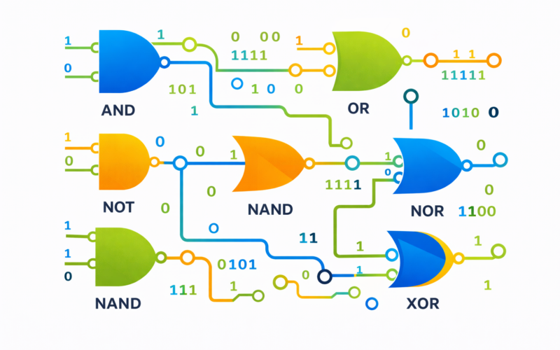
Logic gates are electronic circuits that implement Boolean functions, performing logical operations on one or more binary inputs to produce a binary output. The fundamental gates are:
AND Gate: Outputs 1 only when all inputs are 1. This implements logical AND operation. The truth table shows output is 1 only for the input combination (1,1).
OR Gate: Outputs 1 when at least one input is 1. This implements logical OR operation. Output is 0 only when all inputs are 0.
NOT Gate (Inverter): Inverts its input—outputs 0 for input 1 and 1 for input 0. This is the only single-input gate.
NAND Gate: Combination of AND followed by NOT. Outputs 0 only when all inputs are 1. NAND is universal—all other gates can be built using only NAND gates.
NOR Gate: Combination of OR followed by NOT. Outputs 1 only when all inputs are 0. NOR is also universal.
XOR Gate (Exclusive OR): Outputs 1 when inputs are different. This gate is particularly useful for arithmetic operations.
XNOR Gate: Outputs 1 when inputs are the same. This is the complement of XOR.
Modern integrated circuits contain millions or billions of transistors, but all digital logic ultimately reduces to these basic gates at the transistor level.
Boolean Algebra
Boolean algebra provides mathematical rules for manipulating logical expressions. Unlike ordinary algebra working with real numbers, Boolean algebra works with just two values: 0 and 1.
Fundamental Boolean identities include:
A + 0 = A (OR with 0 leaves value unchanged)
A + 1 = 1 (OR with 1 always yields 1)
A · 0 = 0 (AND with 0 always yields 0)
A · 1 = A (AND with 1 leaves value unchanged)
A + A = A (OR with itself yields itself)
A · A = A (AND with itself yields itself)
A + A’ = 1 (OR with complement yields 1)
A · A’ = 0 (AND with complement yields 0)
(A’)’ = A (Double negation yields original)
De Morgan’s Laws are particularly important:
(A + B)’ = A’ · B’ (Complement of OR is AND of complements)
(A · B)’ = A’ + B’ (Complement of AND is OR of complements)
Absorption laws:
A + A·B = A (Can absorb AND term)
A · (A + B) = A (Can absorb OR term)
These identities enable simplification of Boolean expressions, reducing the number of gates needed to implement circuits and improving performance and reducing power consumption.
Circuit Simplification and Minimization
Karnaugh Maps (K-maps): K-maps provide a visual method for Boolean function minimization. By arranging truth table values in a specific grid pattern, adjacent 1s can be grouped to identify simplified terms. Each group of adjacent 1s corresponds to a simpler Boolean expression.
Quine-McCluskey Method: For functions with many variables, tabular methods like Quine-McCluskey provide systematic approaches to finding minimal forms. Computational tools now handle this automatically for complex designs.
Minimization is crucial because each gate in a circuit consumes power and contributes delay. Reducing the number of gates improves performance, reduces power consumption, and decreases manufacturing cost.
Combinational Logic Design
Combinational circuits produce outputs based solely on current inputs, with no memory. Design steps include:
1. Problem specification and truth table development
2. Boolean function derivation
3. Simplification using K-maps or Boolean algebra
4. Gate implementation
5. Verification and testing
Common combinational circuits include multiplexers (select one of many inputs), demultiplexers (route single input to one of many outputs), encoders (convert input to binary code), decoders (convert binary code to output), adders (perform binary addition), and comparators (compare magnitudes of two numbers).
Sequential Logic
Sequential circuits have memory—their outputs depend on past inputs as well as current inputs. This memory is implemented using flip-flops, which store a single bit of information.
Flip-flops are bistable devices with two stable states (0 and 1). They can be triggered by clock signals or control inputs. Common flip-flop types include SR (Set-Reset), D (Data), JK, and T (Toggle) flip-flops, each with different triggering behavior.
Sequential circuits built from flip-flops enable counters, shift registers, and state machines. These are essential for implementing control logic, managing sequences of operations, and building state-based systems.
Integrated Circuit Technology
Digital circuits are implemented using integrated circuits (ICs) at various scales:
Small Scale Integration (SSI): Fewer than 12 gates per chip. Used for basic gates and simple functions.
Medium Scale Integration (MSI): 12 to 1000 gates. Common components like multiplexers and flip-flops.
Large Scale Integration (LSI): 1000 to 100,000 gates. Memory chips, simple microprocessors.
Very Large Scale Integration (VLSI): More than 100,000 gates. Modern microprocessors, memory arrays, digital signal processors.
Ultra Large Scale Integration (ULSI): Billions to trillions of transistors. Modern processors, GPUs, large memory systems.
Modern VLSI design uses hardware description languages (HDL) like Verilog and VHDL to specify circuit behavior, with computer tools synthesizing the design into gate-level implementations and ultimately into transistor layouts.
Design Considerations
Propagation Delay: Signals take time to propagate through gates. In high-speed circuits, managing these delays is critical.
Power Consumption: Dynamic power consumption (from switching) and static power (from leakage current) must be managed, especially in battery-powered devices.
Noise and Signal Integrity: Electrical noise can corrupt signals. Proper circuit design, impedance matching, and shielding manage these issues.
Testability: Complex circuits require sophisticated testing strategies. Design for Testability (DFT) techniques ensure circuits can be verified to work correctly.
Applications
Digital electronics principles underlie all modern computing. From simple logic circuits to complex microprocessors, the fundamental concepts remain the same. Modern developments include programmable logic (FPGAs, CPLDs), allowing designers to reprogram circuits without changing hardware, and emerging technologies like quantum computers and photonic computing, pushing digital electronics in new directions.
Worked Examples
Example 1: Boolean Algebra Simplification
Problem: Simplify the Boolean expression: F = AB + AB’C + AC
Solution (Step-by-step):
F = AB + AB’C + AC
F = AB + AB’C + AC (Factor out A from last term… actually let’s use different approach)
F = AB + AC + AB’C (Rearrange)
F = A(B + C) + AB’C (Factor A)
F = A(B + C + B’C) (Factor again)
F = A(B + C(1 + B’)) (Consensus theorem)
F = A(B + C) (Since 1 + B’ = 1)
Final Result: F = AB + AC (Reduced from 5 to 2 terms)
Example 2: Truth Table for XOR Gate
Problem: Construct truth table for XOR (exclusive OR) gate with inputs A and B.
Solution:
| A | B | A XOR B |
| 0 | 0 | 0 (both same) |
| 0 | 1 | 1 (different) |
| 1 | 0 | 1 (different) |
| 1 | 1 | 0 (both same) |
Boolean Expression: F = A’B + AB’ (output is 1 when inputs differ)
Example 3: De Morgan’s Law Application
Problem: Apply De Morgan’s laws to simplify: (A + B)’
Solution:
De Morgan’s Law states: (A + B)’ = A’ · B’
Therefore: (A + B)’ = A’ · B’ (NOR gate)
Physical meaning: The complement of an OR is equivalent to AND-ing the complements.
Key Takeaways
- Logic gates are the building blocks of digital circuits—AND, OR, NOT, NAND, NOR, XOR each performing specific logical operations.
- Boolean Algebra provides the mathematical framework for analyzing and simplifying digital circuits using logical operators.
- Truth tables show all possible input-output combinations—essential for understanding gate behavior and circuit design.
- De Morgan’s Laws are critical for simplifying complex Boolean expressions and optimizing circuit designs.
- Combinational circuits have outputs dependent only on current inputs, while sequential circuits have state and memory.
- Number systems in digital electronics include binary, decimal, octal, and hexadecimal—binary is fundamental to computer logic.
- IC technology and HDL languages have revolutionized digital design, enabling rapid prototyping and implementation of complex systems.
Leave a Reply